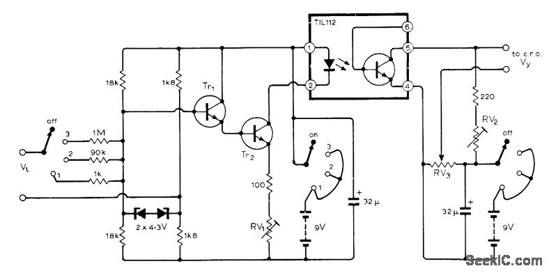

The best optocoupler to use is a high-speed optocoupler with a logic output.

With a greater voltage we have to replace the these resistors with other with higher value (or add externally to the board). The 6N138 uses a photodiode, but its Darlington output is too slow for MIDI unless you add more components (e.g., a base/emitter resistor) to speed it up. In this case we have to pay attention to the value of the resistors R9.11 that are 220 Ohm, chosen for about 5 Volt on P1. It is intended to be a trigger device only. NOTE: This optoisolator should not be used to drive a load directly. Diodes can be 1N4001 resistors, R1 and R2, are optional 330.
OPTOISOLATOR CIRCUIT DRIVER
One more thing that today I add, is that this board can be used as INPUT Interface and not only as OUTPUT. InverseParallel SCR Driver Circuit (MOC3041M, MOC3042M, MOC3043M) 360 Suggested method of firing two, backtoback SCR’s with a onsemi triac driver. If we need to drive more heavy loads more than 500 mA for channel( ) we need to use the output of this board to drive another Darlington board but (pay attention) with PNP inputs! In other words, this board it's very good for conditioning isolated signals or to drive low-medium load. worst than a Darlington if we look at the Ic current that is lower than a Darlington.better than a Darlington if we look at the 'Vce sat.' that is lower than a Darlington.While its not as critical for photo-transistors as it is for 'normal' transistors its. 6) Place the optocoupler IC in the female headers. 5) Connect the 4V DC battery with the circuit. 4) Solder the +ve terminal of the LED with output female header & the -ve terminal with the ground of the circuit. Transistor or photovoltaic output optoisolators use light to transmit information across an electrical insulation barrier, usually for safety or functional.
OPTOISOLATOR CIRCUIT SERIES
The second circuit is doing 'high side switching' and should be done with PNP optocouplers. 3) Solder the Pushbutton in series with the female headers. These stages with a collector of a phototransistor (configured as 'common emitter') connected to the base of the a discrete transistor (configured as 'common emitter') don't make them the same configuration told 'Darlington'. Simply, the transistors in the optocouplers are NPN, so should be used for 'low side switching'. We need also to remember the characteristics of th configuration called also as 'common collector' because it change its gain depending from the load and the output voltage. They could be omitted if you take the output from the emitter of the optocouplers, but (as already told) the emitter can give us a current that is not enough for normal use. The scope of the transistors is only to invert the polarity of the signals at the collector of the optocouplers.


 0 kommentar(er)
